Saturday, November 7, 2015

Performance Management in ETSI MANO

ETSI NFV ISG has defined NFV architectural framework for CSP environment. ETSI NFV architecture has MANO (management & orchestration) components to provide VM life cycle management capabilities. MANO consists of VNF(virtual network function) manager, VNF infrastructure manager (VIM) & traditional EMS(element management system). VNF is responsible of Application virtualization layer events. VIM is responsible for virtual infrastructure layer events, while EMS is monitors application performance.
As shown in figure 1, ETSI MANO consists major management segments:

Figure 1

ETSI MANO Correlation Requirement

In NFV domain, Fault and performance management functionalities are distributed over EMS, VNF manager and VIM. EMS collects Application related counters, VNF manager collects VNF service related counter and VIM collects virtual & physical infra related counters.

To derive end to end performance issues ( as described below) Correlation among VNF Manager, EMS and VIM is highly required, as shown in figure 2.
  • Call drops per VM,  
  • Application performance impact due to failure of particular CPU or, 
  • Utilization ratio of virtual CPU/physical CPU etc, 


Figure 2


Correlation challenges
In traditional Telco network, OSS/BSS platform capture data from downstream EMS directly . Being tightly coupled with hardware, EMS system has end to end view of underneath application and hardware.
In NFV environment Application layer, VNF layer and Virtual Infra layers are based on different technologies and thus have different monitoring systems, different measurement & analytics tools and different Ownership, as shown in figure 3.

Figure 3 


Global VM ID as Correlation Key
The challenge for correlation between Cloud performance data ( VNFM & VIM) and Telecom measurements (EMS) is to find common parameters that can serve as Correlation Keys.
Following are two common attributes, which can be used for correlation across NFV environment:

1) Event Time stamp: time of event occurrence
2) VM_ID (virtual machine ID): virtual machine ID, distributed in VNFD(VNF descriptor).
To utilize VM_ID as correlation key, VM_ID should be unique in entire NFV deployment.

CSP should enforce policy of having unique VM_ID for entire NFV deployment including, NFV orchestration systems, VNF on-boarding, EMS systems, SDN controller, VIM and all other involved tools, and systems.

At time of VM instantiation, NFV orchestrator should obtain VM_ID from global Inventory management. It should distribute VM_ID among NFV MANO elements and downstream SDN controller, during VM instantiation as part of VNFD(VNF Descriptor).
As part of network policy, NFV MANO elements should able to change the VM_ID during scenarios as Inter/Intra host live migration, VM evacuation, etc . Henceforth NFV elements will use the unique VM ID during entire VM lifecycle management.
Following Figure shows the VM ID distribution, User Request can be manual request from Dashboard Or API call from another system, as shown in figure 4
Figure 4


USE CASE : VM_ID based Fault Management Correlation

Following use case describes need for correlation among Application EMS, & VIM to assess performance impact of failure of Physical CPU’s scheduler on VM application performance.
As shown in figure 5:


  1. Application EMS sends call events to Analytics manager. Report IE(information element) contains VM_ID=ABCD, timestamp, Application ID= vMME Release code: Drop etc. Analytics manager calculates the KPI, and finds out call drops for VM_ID is exceeding 0.1% (KPI threshold) per hour.
  2. VNFI forwards virtualization layer & hardware related alerts to Analytics Manager.
  3. Correlation engine at Analytics Manager correlates the EM alerts and VNFI alerts, finds that VM_ID ABCD is observing physical CPU scheduler fault, which is resulting in increased drop calls.
  4. Analytics manager co-ordinates with Policy manager for resolution.
  5. Policy manager forwards rule to migrate the VM to new location for VM_ID ABCD.
  6. Analytics Manager Co-ordinates with Inventory Management to get hardware details for new VM. Hardware details include new VM location ( node, line card & VM number), RAM, CPU & Memory details as described in VM affinity rules in VNFD. New VM_ID will be based on new location.
  7. Analytics Manager will forward the details to VNFI manager.
  8. VNFI manager instruct hypervisor to spawn new VM, with VM ID as XYWZ.

Reference
  • Network Functions Virtualization (NFV); Infrastructure Overview(GS NFV-INF 001)
  • Network Functions Virtualization (NFV); Architectural Framework(GS NFV 002) Network Functions Virtualization (NFV); Management and Orchestration(GS NFV MAN 001)
  • Network Functions Virtualization (NFV); Virtual Network Functions Architecture(GS NFV SWA 001)

This blog represents personal understanding of subject matter.

What is VNF Silo ???

VNF (virtual network function) is composition of one or many VMs to realize Telecom network function on virtualized platform. 

Definition of VM, VNF and Virtual Service is specified in ETSI GS NFV 002 as shown in Figure 1:
Virtual Machine (VM): virtualized computation environment that behaves very much like a physical computer/server. A VM has all its ingredients e.g processor, memory/storage, interfaces/ports etc of a physical computer/server and is generated by a Hypervisor.

Virtual Network Function: A VNF is a virtualization of a network function , e.g. EPC functions such as Mobility Management Entity (MME), Serving/Packet Gateway (S/P GW) ; and conventional network functions such as DHCP servers, firewalls, etc. VNF lifecycle events are managed by VNF Manager.

Virtual Service: Combination of various VNFs form virtual service e.g virtual VoLTE, by integrating IMS VNFs & EPC VNFs.
Figure 1:


VNF Architecture
The VNF architecture depends on VNF Provider’s strategy . For example, one VNF Provider may implement a VNF as a monolithic, vertically integrated single VM, while another VNF Provider may implement the same VNF by, decomposing application functions into separate VMs, as shown in figure 2.
Figure 2:
 

Monolithic VNFs are easy to deploy since less VMs required to instantiate, hence simpler task for NFV orchestrator. While decomposed VMs brings complexity in VNF instantiation, it also provides opportunity to introduce open source elements into VNF Architecture. e.g using No-SQL database instead of Telco application’s proprietary database to preserve application state, once state persistence is decoupled from Application logic. 

Decomposition brings software modularity and provides opportunity for VNF reusability.

Decomposed VNF Architecture
The objective behind designing VNF is to hold software functionality, while decomposing software into manageable modular blocks and decouple software from hardware. Figure 3 shows one example of VNF decomposing. 
Figure 3
In Legacy world, Telco software components are deployed on proprietary Line Cards(LC), where LCs are installed in hardware shelf. These LCs are interconnected by backplane switches to make internal communication possible. While in NFV world, software will be deployed on virtual machines and VMs will be interconnected by virtual Switch ( e.g OpenVswich, vRouter) and chaining of VMs will form VNF to realize element functionality, as shown in figure above.

VNF Reusability
In legacy world application’s software is written for particular hardware, and hence to reuse it’s component for another hardware required time-consuming customization. Thus CSP’s network converted into plethora of hardware boxes, each running specific application to offer specific functionality.

In virtual world, VNF Decomposition offers opportunity for VNF reusability. As software becomes more modular and decoupled from hardware, it’s components can run on industry standard hardware with little or no customization. This will make service deployment faster. 

As shown in figure below, GTP handing VM is reused in EPC core, with minimum customization.
Figure 4


Further down the line, We can present software modular blocks as service catalogue and application developer can pick & choose, necessary functions to design application.

VNF On-Boarding
VNF on-boarding means procedures to instantiate VNF in cloud environment. 
Following points to be noted in order to design VNF on-boarding :
  1. VM instantiation flow (Booting Order) e.g sequential or parallel instantiation of VMs
  2. Service chaining of VMs in order to realize VNF functionality e.g VNF Architect should have good understanding of packet traversal in VNF chain & individual VM’s functionality, in order to create service chaining.

Figure 5, shows high level steps for VNF on-boarding:

  1. User logs in VNF catalog GUI and raises request for VNF.
  2. Template Generator will generate Heat or Tosca template based on request. This also called VNFD(VNF descriptor), as defined by ETSI. Tosca required to convert to Heat template (HOT) eventually.
  3. Cloud Orchestrator e.g. Openstack will instantiate VNF, by co-ordinating with Virtual Infra manager, for compute, network and storage requirements, as described in HOT. Template will also define Affinity rules such as VM’s placement on physical host for HA requirement.
  4. Orchestrator will also co-ordinate with VNF manager to service chain VNF as described in HOT.
  5. Once VNF is instantiated successfully with required resources and network, EMS system will configure the application, hosted on VMs. 
VNF’s compute(RAM, Memory etc) , Storage, Networking(vNIC ports), Affinity rule(Physical host selection for VM), Auto healing mechanisms, Service chaining details etc are prescribed in VNF Template. Cloud Orchestrator will instantiate the VNF based on VNF template. This template can be HOT (heat template) or TOSCA(Topology Orchestration Specification for Cloud Applications). TOSCA template can be converted into HOT for openstack based cloud orchestration.( https://github.com/openstack/heat-translator).

VNF Silo
Primarily VNF manager is responsible for managing VNF lifecycle. VNF manager can belong to VNF provider solution such as contrail for Juniper products, Ericsson Cloud Manager etc. Problem with this approach is VNF Silo.

Consider a service such as VoLTE consist of multiple VNF providers as Ericsson, Alcatel Lucent, Cisco, Juniper.. and each VNF provider comes with own VNF manager. This will create VNF Silo as shown in figure below.

Figure 5

Concept of Open VNF manager is one of the solution, where singular VNF Manager interacts with cloud orchestrator using Heat & Tacker APIs. Open VNF manager framework consists Vendor plugins to manage their VNFs. Tacker is a generic VNF manager service for Openstack managed Cloud. More details are https://wiki.openstack.org/wiki/Tacker


Reference
ETSI GS NFV 003 V1.2.1 (2014-12): NFV Terminology
ETSI GS NFV 002 V1.2.1 (2014-12): NFV Architectural Framework
ETSI GS NFV-SWA 001 V1.1.1 (2014-12): NFV Virtual Network Functions Architecture.

(This blog represents my personal understanding of the subject matter).

Sunday, October 4, 2015

Recursive SDN Architecture for scalability


In this post, I will explain SDN recursive architecture to meet carrier grade scalability requirement.

Background
For scalability, typical ISP network is designed in 3 tier architecture as shown in figure below:

Traffic from multiple access points, gets aggregated by the L2 Metro Ethernet before going to the IP Edge network. All traffic types are backhauled to a BNG (Broadband Network Gateway) before going to a PoP (Point of Presence) or P-Router location that is connected to the ISP backbone. The BNG, which is deeper in the network, executes multicast replication, subscriber termination functionality, and IP QoS policies. For Broadcast video's IP Multicast, the traffic starts from the edge router and is transmitted to customer premises over L2 multicast VLANs.
Three tiered hierarchical architecture provides required scalability, by adding  L1 access points and  L2 Aggregation points as traffic grows.
Each network components, in above mentioned 3 tier hierarchical network, control plan in embedded in same hardware as data plane, as shown in figure 2. Tight coupling of Control & Data plane in single proprietary box, restricts CSP’s capacity to innovate, brings new features in networking, etc.. To develop any feature CSP has to rely on their EV partner, which follows its own product release cycle, regardless of CSP’s requirement.
 
Concept behind SDN controller is to decouple control plane & data plane by separating packet policy from packet forwarding as shown in figure below. This architecture will bring abstraction into networking domain. Networking abstraction will bring new ideas and opportunities in networking domain e.g Big data analytics on real time traffic,  Traffic specific routing, Application based on L7  policy control. Due to SDN based decoupling, CSP can develop networking applications in feature rich Java or similar languages (the way developers write Android applications, without need to know much about phone hardware).

SDN Scalability
Prime concern behind SDN deployment is carrier grade scalability. SDN Architecture has to offer scalable solution for large scale CSP(as shown in figure 10).
Proposed use case is to deploy SDN controller to configure & manage virtual network elements as vSwitch, vRouter or OpenVSwitch residing in hypervisor to manage east/west (intra vDC) and north/south traffic (inter vDC).  Problem with this arrangement is scalability.
Consider CSP is having 4 virtual datacenters(vDC) namely A,B,C &D. Each datacenter is managed by respective SDN controller. To provision Layer 7 load balancing or firewall, policy for an application, CSP requires to configure each SDN controller individually. Now consider large CSP with thousands of Data centers globally with hundreds of SDN controllers managing them. This sort of individual policy configuration does not scale, as shown in figure below.


SDN architecture has to scale the way current 3 tier data plane architecture scales (figure 1) to meet carrier grade deployment.  Here comes concept of Global SDN, or Master SDN or SDN Gateway.
Global SDN
Global SDN will have end to end topology view of entire network and it provides following features
1)      Global policy configuration
2)      Layer 4-7 Application (Firewall, Load Balancer etc) configuration
3)      PNF (Physical/Legacy network function) configuration.
4)      Virtual DC selection for VM placement
As Global SDN has complete topology and vDC capability view, it can choose correct vDC for application VM placement. Another important aspect of Global SDN is it’s ability to integrate with Legacy Network elements(PNF). This is much required capability, as CSP network will consist legacy network elements for foreseeable future, thus for Global policy management, integration with those legacy boxes is much required. As shown in figure below, high level architecture of Global SDN will consist of various policy, layer 4-7 application, Traffic Engineering applications at North bound, while vDC SDN controller’s & PNF’s plugins at South bound. 
 
SDN Recursiveness
Recursion is the process of repeating items in a self-similar way. A visual form of recursion known as the Droste effect(figure above) . The woman in this image holds an object that contains a smaller image of her holding an identical object, which in turn contains a smaller image of herself holding an identical object, and so forth.
 
Recursive Architecture enables single, tunable protocol for different layers of the protocol stack, reusing basic protocol operations across different protocol layers to avoid reimplementation. In telco networking terms, recursion can be used to describe packet forwarding workflow, from access switch line card to core switch. Similar workflow of lookup is repeated at each network points from access to edge to core i.e from lowest layer(access switch line card)  to highest layer (core switch).
The way current ISP PoP architecture is designed, SDN recursiveness can implement SDN hierarchy as shown in figure below starting from Local SDN controllers at Tier 0, Area SDN controllers at tier 1 and finally Global SDN at top most position in hierarchy. Each layer will work on similar logic and workflow as previous one , while abstracting details, from higher layer. This abstraction will make sure only necessary metadata will be sent at higher layers and this will bring policy & failure locality as well as required scalability.

 
SDN recursive architecture implements aggregation function by aggregating  state changes of tier-0 SDN controller towards Global SDN controller. Similarly fan-out function can distribute global policy configuration towards tier 0 SDN controllers.  Each level of recursion can aggregate the information traveling upwards through the hierarchy, and “fan out” information traveling down through the hierarchy. For example, vDC can aggregate vDC port details to Area SDN controller, while Area SDN controllers can aggregate links(connected by Port) details for Global SDN. And Global SDN can aggregate all links information create end to end network topology view. Similarly Fan Out function can implement Global policy update from Global SDN controller to vDC SDN controller as shown in figure below:
 
Summary
Proposed  SDN deployment has policy & configuration locality and does not have entire network topology view, which restricts their functionality to Layer 2&3 only. This also limits required carrier grade scalability. To scale SDN architecture to accommodate layer 4-7 functionality and Global policy update, Global SDN controller is conceptualized. SDN recursive hierarchy  will bring ISP PoP like geographical spread of SDN controllers, where Global SDN controller will be in  top-most position and vDC SDN controller will be at tier-0.
Reference

This blog represents my personal understanding of the subject matter).


Thursday, August 6, 2015

4 key steps of SDN Roadmap for CSP


In telecommunication, Software Defined Networking(SDN) is part of 5G future. Most of Telecom gurus have agreed on a fact that SDN will be next Gen telecom technology. Now discussion is moving towards Roadmap. How to reach there & what kind of future it will be, where NFV & SDN will be dominating in-production technologies in CSP network ?

 
Following are 4 key evolution steps for SDN roadmap.. Some companies have already started towards that direction e.g. AT&T’s Network On Demand offering (http://www.business.att.com/enterprise/Family/network-services/ethernet/#fbid=ZxCUMw9K4KM?hashlink=tab2)   

 1st Step: Service Provisioning

Concept as SoA (service oriented architecture) has been implemented in CSP’s OSS environment to integrate various OSS elements in pre-SDN era e.g. Zero touch provisioning.  Those were limited to Layer 7 only. OSS & Network NMS, was two discrete systems, call it IT & Telecom. There was no integration between system which takes customer order (OSS) and system which executes customer order(NMS).

SDN movement has broken the barrier. By creating bridge between high level OSS messages and low level routing protocol, entire service delivery workflow nearly automated, as shown figure below. Mind that OSS environment requires fine tuning to be SDN compatible. TMForum has initiated project ZooM https://www.tmforum.org/zoom/ ). ZOOM  is Zero-touch Orchestration, Operations and Management.


2nd Step: Service Virtualization
Second step is to decouple data plane and control plane, by virtualization i.e NFV.  Once Software is decoupled from hardware, it can be hosted on cloud as virtual instance.  These will pave way for White box elements as forwarders, Switches and CPEs. We call it white box elements, because their intelligence is residing in the cloud, while they act as merely data forwarders. Decoupling will also commoditize data plane and routing/switching software can be hosted on any generic X86 COTS hardware.
 
 
3rd Step: Service Centralization
Since routing/switching software is separated, Virtual control plane can be centralized.  Now SDN controller can control data plane forwarding, by using protocol as Openflow. Centralization of routing intelligence will unlock many possibilities as WAN optimization, on-fly routing decisions, scaling  bandwidth between nodes e.g proactive bandwidth Calendaring etc. Currently bandwidth scaling between two CSP peers are time & resource consuming because of their multivendor environment & autonomous systems. With centralized SDN controller, bandwidth calendaring will be much easier.  One can integrate Big Data based analytics Apps at northbound interface of SDN, to analyze the traffic pattern for optimizing  the transport network like never before.  
 
 
4th Step: Service Decomposition
Virtualization will decouple hardware from software, and decomposition will further modularize software to remove duplicate functions in service workflow. The intent is to reduce packet capsulation and de-capsulation in packet forwarding path.
Decomposition at Data plane..
Hardware limitations constraint SDN's configurability. To deal with this, Telco industry is working on Programmable Data plane. We need faster software and programmable hardware. Princeton university is working with concept, called  NetASM (http://www.cs.princeton.edu/~mshahbaz/sites/netasm/) to provide necessary hardware abstraction layer, where underlying hardware capabilities are completely  abstracted from SDN controller/services above. Hardware abstraction layer will enable domain specific language as P4 (https://en.wikipedia.org/wiki/P4_(programming_language) to program underlying hardware.
 
 
Decomposition, along with programmable hardware, will change entire Telco network landscape. Packets will traverse less ports & services can hop from one to another cloud, without any sort of code change. With more flexibility, complexity will increase too & those complexities will lead telecom world to newer technological frontiers.

Thanks for attention..


Thursday, July 9, 2015

What CSP wants from Neutron !!! (Part 1: DVR)


Openstack Neutron project provides API abstraction to manage network elements in cloud environment.  CSPs as AT&T, Verizon etc has shown interest in deploying Telco Cloud, based on Openstack orchestration. They have certain key requirements from Neutron to give carrier grade  performance & scale.

Key requirements are :

1)      DVR (distributed virtual router)

2)      Dynamic Routing

3)      VLAN trunking

DVR (distributed virtual router)

To understand DVR, we need to understand:  

-        Source NAT: Network Address Translation is an Internet standard that allows hosts on local area networks to use one set of IP addresses for internal communications and another set of IP addresses for external communications. A LAN that uses NAT is referred as natted network. Source NAT is performed on packets that are originated from a natted network. A NAT router replaces the private source address of an IP packet with a new public IP address as it travels through the router. A reverse operation is applied to the packets travelling in the other direction. This way Network administrator hides source IP address before entering into public network.

 
-        Destination NAT: Destination NAT is performed on packets that are destined to the natted network. A NAT router performing destination NAT replaces the destination IP address of an IP packet as it travel through the router towards a private network. This way Network Administrator hides destination IP address before entering into private network.

IP packet format is shown below. When firewall hides Source IP address, it called SNAT, and when it hides destination, it called  DNAT.


       Floating IP: Floating IPs are just publicly routable IPs that you typically buy from an ISP (the one that you put on the firewall in the above example). Users can allocate them to their instances, thus making them reachable from the outside world. Floating IPs are not allocated to instances by default. If an instance dies for some reason, the user does not lose the floating IP—it remains his own resource, ready to be attached to another instance. Router performs the Destination NAT (DNAT) to rewrite packets from the floating IP address (chosen from a subnet on the external network) to the internal fixed IP (chosen from a private subnet that is behind the router).


-        East West Traffic: East-West traffic is primarily comprised of communication between applications hosted on physical and virtual machines, and VM to VM interactions within the DC. “North-South” traffic is primarily composed of traffic that enters and exits the DC, and generally includes queries, commands, and specific data either being retrieved or stored.
Problem Statement
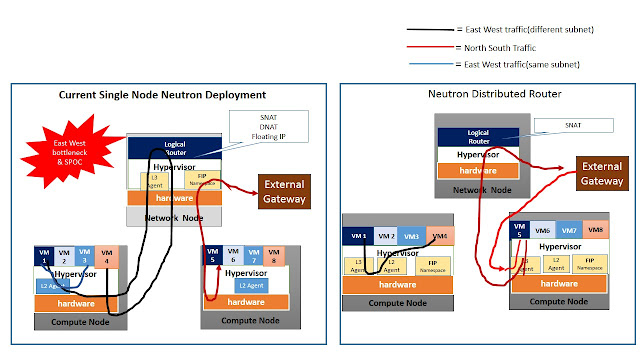
Today Neutron L3 Routers are deployed in specific Nodes (Network Nodes) where all the Compute traffic will flow through. This lead to following bottlenecks:
-        East West Traffic
VMs traffic that belong to the same tenant & same subnet, switched by native hypervisor’s L2 agent, but traffic on a different subnet has to hit the Network Node to get routed between the subnets. This because L2 agent can’t route based on Layer 3 IP address. Hence traffic on different subnet, even if destination VM is residing on same physical server has to forwarded to Network node, where Layer 3 agent resides. This would affect Performance.
-        North South Traffic
As mentioned earlier, Floating IP are routable public IPs and mapped to private IPs. Today Floating IP (DNAT) translation done at the Network Node. External network gateway port is available only at the Network Node. So north south traffic i.e. traffic intended for the External Network from the VMs have to go through the Network Node. In this case the Network Node becomes a single point of failure (SPOC)  and also the traffic load will be heavy in the Network Node. This would affect the performance and scalability.
 
Solution
L3 agents with DNAT functionality and Floating IP name space should be part of Compute node. Distributed Virtual Router implements the L3 agents across the Compute Nodes, so that tenants’ intra VM communication(East-West traffic)  will occur without hitting the Network Node. Neutron Distributed Virtual Router implements the Floating IP namespace on every Compute Node where the VMs are located. In this case the VMs with Floating IPs can forward the traffic to the External Network without reaching the Network Node. (North-South Routing).
See figure below:
 
Solution Implementation
-        Current ML2 L3 agents should be running on each and every compute node. Existing L3 agents required to be DVR aware. New enhanced L3 agent should be working on “centralized”(existing network node) and “Dvr”(on compute node) mode.
-        Enhanced L2 agent e.g L3 plugin for OpenVswitch. OpenVswitch should interface with L3 plugin to acquire routing capabilities.
-        Enhanced Neutron REST API for DVR
Reference:
 ( VLAN trunking & BGP routing will be explained in next posts)


Thursday, May 14, 2015

What is Openstack Orchestrator !!


French word Orchestrator originated  from “Orchastra”. Orchastra means group of music performers and orchestrator is to compose or arrange music for performance e.g.  planning/sequencing/harmonizing performance of performers for the audience.

In cloud computing world, Orchestrator is system manager which arranges complex workflows among various cloud elements, to realize user request.

 Openstack Orchestrator
 
Openstack provides API framework for cloud management. Openstack Cloud Orchestration is synchronized  workflow among services  as Nova(Compute), Neutron(Network), Glance (Image), Keystone(Identity), Storage(Cinder & Swift), Dashboard(Horizon), Heat(Orchestration template) ) to realize cloud VM lifecycle management, e.g VM instantiation, live migration, VM deletion, VM suspension etc, as shown in figure below:

 When Openstack Orchestrator receives request , it triggers following chain of actions:  

1)      Service request for VM provisioning from Horizon(dashboard) from CLI, Horizon or via Heat template

2)      Service is authenticated by Keystone

3)      Nova service interacts with compute node’s hypervisor to reserve the required virtual resources.

4)      Nova service interacts with Cinder node to reserve required storage capacity for VM

5)      Nova service interacts with Neutron node/SDN plugin  to create network(IP address/DHCP) for the VM

6)      Neutron service co-ordinates with L2 & DHCP agent, to get network details. Network details passed to Nova via MQ.

7)      Nova service interacts with Glance to download required guest OS image for VM

8)      Nova service notifies User about successful VM instantiation

Openstack Orchestration platform will carry out above mentioned activities in sequential & harmonized manner to provision a virtual machine, as shown in figure below. (more details at https://bugs.launchpad.net/openstack-manuals/+bug/1359722 ).  
 

 Openstack Interaction
Openstack services interact with cloud infrastructure at various touch-points, as below:   

 
Application

Application will interact with Openstack at Guest OS level.
Application’s OS image should be available in  Glance image repository. Orchestration will download it during VM provisioning. In other words, Application’s touch-point with Openstack Glance service is through guest OS Image.
DPDK aware Applications connect to user-space directly and bypass Guest OS. In this scenario, Neutron supposed to provide virtual Switch ports, which supports DPDK. This requirement should be specified in image Meta data or via Heat Templates.

Hypervisor

-        Openstack services interacts with Libvert drivers to communicate with Hypervisors. Openstack Nova interacts with Libvert to reserve virtual resources (CPU, RAM) for VM and Neutron interacts with Libvert to get OpenVswitch/VRouter port details. Thus any new feature in hypervisor (DPDK, Cpu pinning etc) requires some modification in Libvert drivers.
Network

-        Openstack provides Neutron APIs to interact with networking elements. Networking  Vendors (Cisco, Arista, Juniper) have developed Plugins to communicate with Neutron. Using Plug-ins and Neutron API services, Openstack Orchestration should be able configure various agents (Open Vswitch/vRouter), residing in hypervisor. These networking agents configure traffic among VMs and traffic to external gateway. Thus networking team requires their plugin to be fully interoperable with neutron API service.

-        Neutron has possibility to interact with SDN controller (e.g Opencontrail), which controls  network agents. In this scenario, network configuration can be done by SDN controller or Openstack.. This demarcation of responsibilities between SDN and Openstack is required.


Openstack Orchestrator is kind of system manager which deals with complex system workflows in cloud environment.